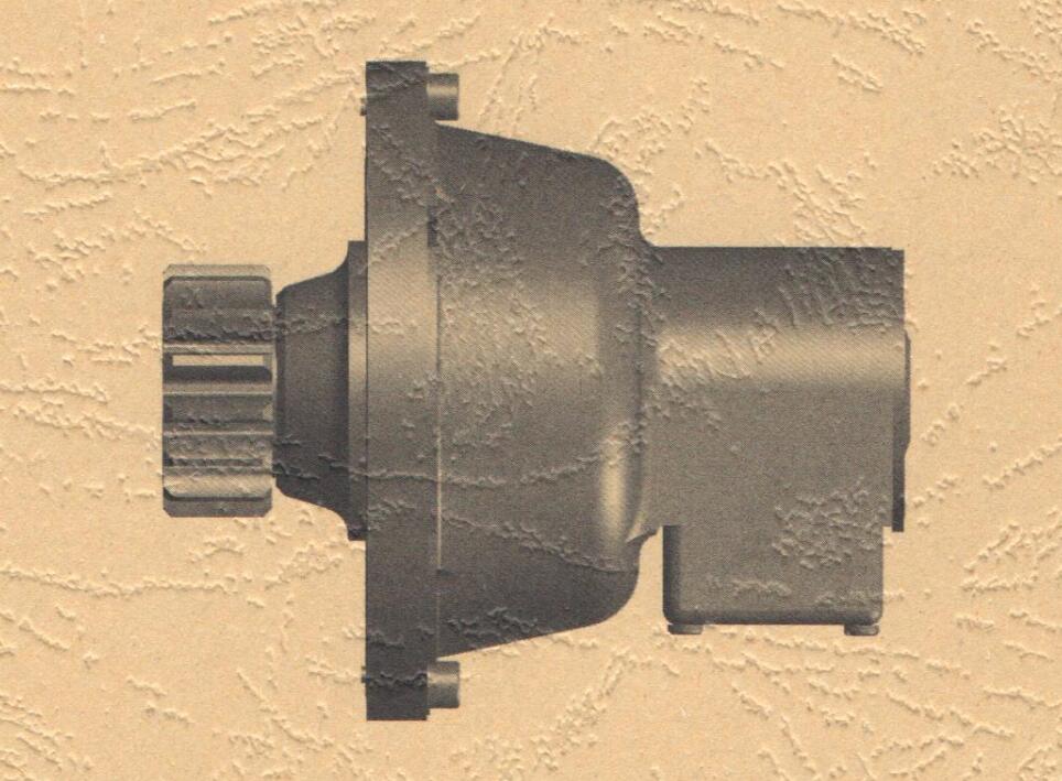
SAJ Serials Pinion and Cone Progressive Safety Device
Operation Instruction
(Please read this manual before using )
Jiaxing Jingyang Construction Machinery CO. of Zhejiang Jiaxing Research
Institute of Building Sciences
www.jingyangroup.com
01/01/2014
A: Introduction
SAJ serials pinion and cone progressive safety device is the most important safety component of builders hoist, which can prevent cage running over speed and effectively decrease the probability of cage dropping accident.
The safety device developed by Shanghai Research Institute of Building Sciences has passed through the identification, which is presided by the Ministry of Construction in 1989. Experts attending the meeting made a high appraisal of the safety device, because of its reasonable structure, high precise processing, stable tripping speed, safety and reliability, braking smoothly and light weight etc. The device was recommended as high-tech products by the Ministry of Construction in National Eighth Five Year Plan?and also won the Excellent New Products Achievement Award of Shanghai Municipality
B: Main technical performance parameters and installation dimensions Parameter List refer to The Table One and Fig. 1 (page two and page three)
Declarations of Table One
1:Five models of safety device with no release device,
SAJ02-1.2, SAJ08-1.2, SAJ30-0.5, SAJ30-1.2, SAJ30-1.4.
2:Five models of safety device engaged with two transition gears,
SAJ40-2.0, SAJ50-2.0, SAJ60-1.2, SAJ60-2.0, SAJ70-1.4.
3:L4 denotes the distance from gear center to pitch line of rack.
4:Z denotes tooth number of gear, m denotes gear modulus. The gear modulus of SAJ02-1.2 and SAJ08-1.2 is 4 and 5. The others are 8.
5:Provide special gear shaft based on customer requirements.
6:When SAJ02-1.2 is transmitted by sprockets the number of tooth and pitch is 12 and 21.
TABLE ONE: Main Technical Performance Parameters and Installation Dimensions
| ModelParameter | SAJ02-1.2 | SAJ08-1.2 | SAJ30-0.5 | SAJ30-1.2 | SAJ30-1.2A | SAJ30-1.4 | SAJ30-1.6 | SAJ40-1.2A | SAJ40-1.4 | SAJ40-2.0 | SAJ50-1.2A | SAJ50-2.0 | SAJ60-1.2 | SAJ60-10 | SAJ70-1.4 | |||||||||||||||||||||
| Rated braking load kN | 2 | 8 | 30 | 40 | 50 | 60 | 70 | |||||||||||||||||||||||||||||
| Rated braking speed m/s | 1.2 | 0.5 | 1.2 | 1.4 | 1.6 | 1.2 | 1.4 | 2.0 | 1.2 | 2.0 | 1.2 | 2.0 | 1.4 | |||||||||||||||||||||||
| Standard action Speedm/s | According to hoist rated lifting speed and user requirements | |||||||||||||||||||||||||||||||||||
| Weight Kg | 4.6 | 11.5 | 44 | 35 | 50 | 56 | ||||||||||||||||||||||||||||||
| Installation Dimensions (see Fig.l) | D1 | Φ92d9 | Φ100d9 | Φ150 | Φ140 | Φ150 | Φ140= | |||||||||||||||||||||||||||||
| D2 | Φ134 | Φ196 | Φ284 | Φ330 | ||||||||||||||||||||||||||||||||
| D3 | Φ155 | Φ220 | Φ310 | Φ360 | ||||||||||||||||||||||||||||||||
| D4 | Φ11.5 | Φ13 | Φ15 | Φ17 | ||||||||||||||||||||||||||||||||
| D5 | Φ68 | Φ75 | Φ120 | Φ96 | 0120 | Φ96 | ||||||||||||||||||||||||||||||
| D6 | \ | 113.1±0.027 | \ | 113.1±0.027 | ||||||||||||||||||||||||||||||||
| L | 140 | 179 | 311 | 257 | 352 | |||||||||||||||||||||||||||||||
| LI | 16 | 23 | 27 | 33 | ||||||||||||||||||||||||||||||||
| L2 | 21.5 | 31.5 | 43 | 45 | ||||||||||||||||||||||||||||||||
| L3 | \ | 55 | \ | 55 | ||||||||||||||||||||||||||||||||
| L4 | 34 | 37.5 | 60 | 64 | 60 | 64 | ||||||||||||||||||||||||||||||
| Z | 17 | 15 | 12 | 15 | 12 | |||||||||||||||||||||||||||||||
| m | 4 | 5 | 8 | |||||||||||||||||||||||||||||||||
C:The installation of SAJ-type safety device
1:The installing bolts performance level is permitted not less than 8.8. When installing, they should be evenly tightened. SAJ02-1.2 use the bolt specification of M10, SAJ08-1.2 use the bolt specification of M12, SAJ30-0.5, SAJ30-1.2, SAJ30-1.2A and SAJ30-1.4 use the bolt specification of M14, the other type safety device use the bolt specification of M16.
2:The safety device should be checked after installation. The backlash between the safety device gear and the rack of SAJ02-1.2 and SAJ08-1.2 should be held 0.3 〜0.7mm.The other type is 0.5〜0.8mm.
3:The closed limit switch of safety device must be accessed to the liffs control circuit; otherwise it will cause serious consequences.
Drop test and recovery
The safety device is required to take drop t est according to the standard of builders hoist.
1:Drop test steps(for reference only)
The following method is for reference only. Specific operation is subject to the instruction of builders hoist.
Switch off the main power supply and turn the electric cabinet switch to “INSTALLATION OVERHAUL” location.
Install test cable and connect it to the wiring base with “DROP TEST” mark in the cage electric cabinet.
Fix the test cable near to the cage electric cabinet, put operation box and remaining cable onto the ground through door or other suitable hole. Make sure that the cable will not be jammed while the drop test is carried out.
Load rated weight in cage, turn on the main switch, push the “UP” button in operation box, and drive the cage to 10 meter high from ground.
Push “DROP TEST” button and keep pressing, at this time release the electric-magnetic brake, the cage should drop downwards. When dropping speed reaches the tripping speed of the safety device, it would act immediately and stop the cage on the rail support. (Attention: If the cage drops to 3 meters high from ground, and the safety device does not stop the cage,tester should release the “DROP TEST” button to ensure that the electric-magnetic brake stops the cage.)
Disassemble the test cable and turn the switch to“NORMAL” location.
2: Recovery of the safety device
Except drop test, if the safety device acts, we should find out the reason, at the same time the followings should be identified:
Whether the brake works normally.
Whether the turbine pair and the coupling work normally.
Whether the guide rolling wheel and support rolling wheels work normally.
Whether pinion and the rack work normally.
Whether limit switch on the safety device works normally (the electric circuit should be switched off through inspection).
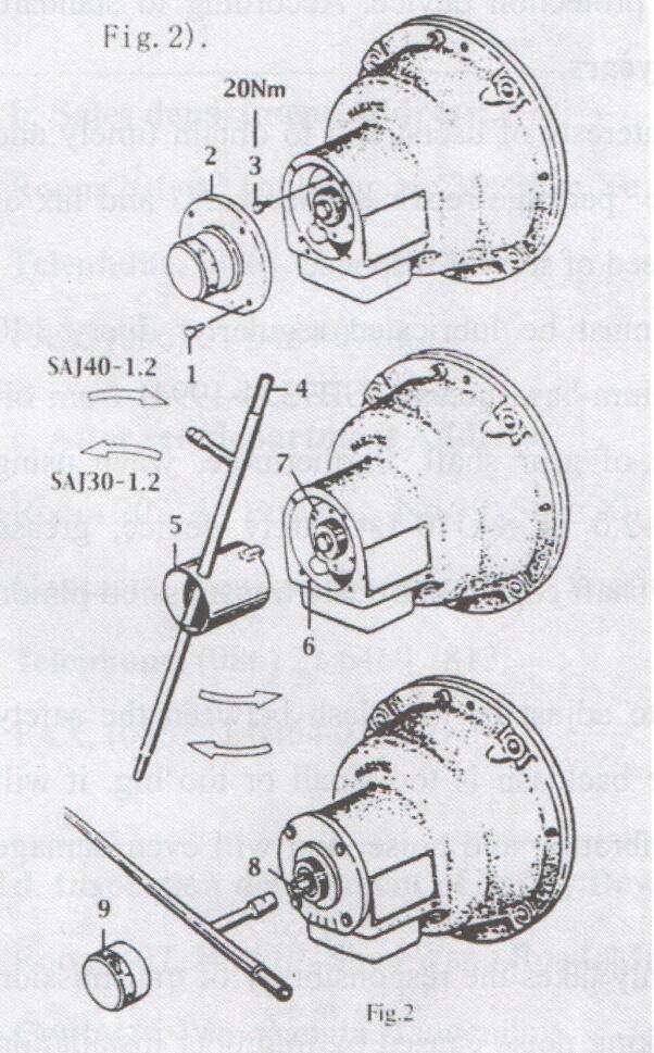
After inspection, make sure that three-phase power supply is cut off and the safety device should be recovered according to the following steps (as shown in Fig.2).
Loosen screw 1,remove cover 2, and loosen screw 3, use a special spanner and pinch bar 4 to loosen copper nut 7 until the end of pin 6 reaches the safety device shell opened side plane (at this time switch on the limit switch electric circuit).
Assemble screw 3 and cover 2 (for end release structure type safety devices, the hood cover 9 should also be removed, the bolt 8 shall be screwed by hand as far
as possible, then use the special tool 4 to screw the bolt 8 for 30 degree angle and release a little, and mount the hood cover 9), turn on the three phase switch, lift the cage to run upwards over 20 cm to recover the centrifugal block.
Cautions
1: Whether safety device is used or not, inspection should be carried out once a year. It can be used only within the validity period after passing annual inspection.
2: Special attention: It is strictly prohibited to carry out drop test twice in 15 minutes for overheating.
3: The inspection is undertaken by the appointed department, Shanghai Research Institute of Building Sciences Co. Ltd.
4: The user is not allowed to open safety device without permission, even lead sealing. Otherwise the manufacturer would not take any responsibilities for any accidents.
5: The product guarantee period is one year (limited to domestic sales).
6: The safety device is an important protection device. According to standard requirements, the effective use period is 5 years.
7: Special attention: To protect the interests of users, and to obtain timely and quick after-sales service, please fill out the “package repair service card” and fax or mail to the company, or it may affect the speed of service response.
8: Special attention: Safety device must be lubricated regularly. Every 120 working hours, we should inject No.2 lithium-base grease (GB7324-1994) from oil cup which is installed in the end surface of gear shaft. Furthermore, when using SAJ40-2.0, SAJ50-2.0, SAJ60-1.2 SAJ60-2.0 or SAJ70-1.4 safety device, grease should be filled through oil hole on support shaft edge to lubricate transmission pinion bears.
9: Special attention: It is important to adjust the backlash between the safety device’s gear and the rack properly. If the backlash is too small or too big,it will result in meshing interference, abnormal vibration and noise, and will even damage the safety device.
10: Special attention: Manufacturer only takes the responsibility of transmission pinions5 quality. The bear wearing and working noise caused by improper installation and operation are not guaranteed to the after-sales service by manufacturer.
11: Special attention: Without permission, the user could not adjust the location of position limited structure and ping 4 in fig.2. After safety device taking action, at first, the activation causes should be investigated, then the safety device could be reused only after all the faults are fixed and safety device recovered based on the above instructions. It is strictly forbidden that safety device keep operation without correct recovery after action.
Contact Us
Warranty department: Jiaxing Jingyang Construction Machinery Co. , Shanghai Research Institute of Building Sciences
Address, No.1111,xiehe park, nanhu district, jiaxing of Zhejiang province, China. (Post code: 314000)
Sales department Address: Jiaxing Jingyang Construction Machinery Co. , Shanghai Research Institute of Building Sciences
Telephone, (086)0573 84187637 FAX, (086)0573 84187636
After sale. department Address:
No.1111,xiehe park, nanhu district, jiaxing of Zhejiang province, China. (Post code: 314000)
Telephone, (086)0573 84187637 FAX, (086)0573 84187636
Inspection department of Safety Device Address,
No.1111,xiehe park, nanhu district, jiaxing of Zhejiang province, China. (Post code: 314000) Telephone, (086)0573 84187637 FAX, (086)0573 84187636
Post time: Jun-30-2019


