Chinese wholesale Iso Bearings To Cranes Bridge - GJJ passenger hoist slider bus bar – Jinyang Detail:
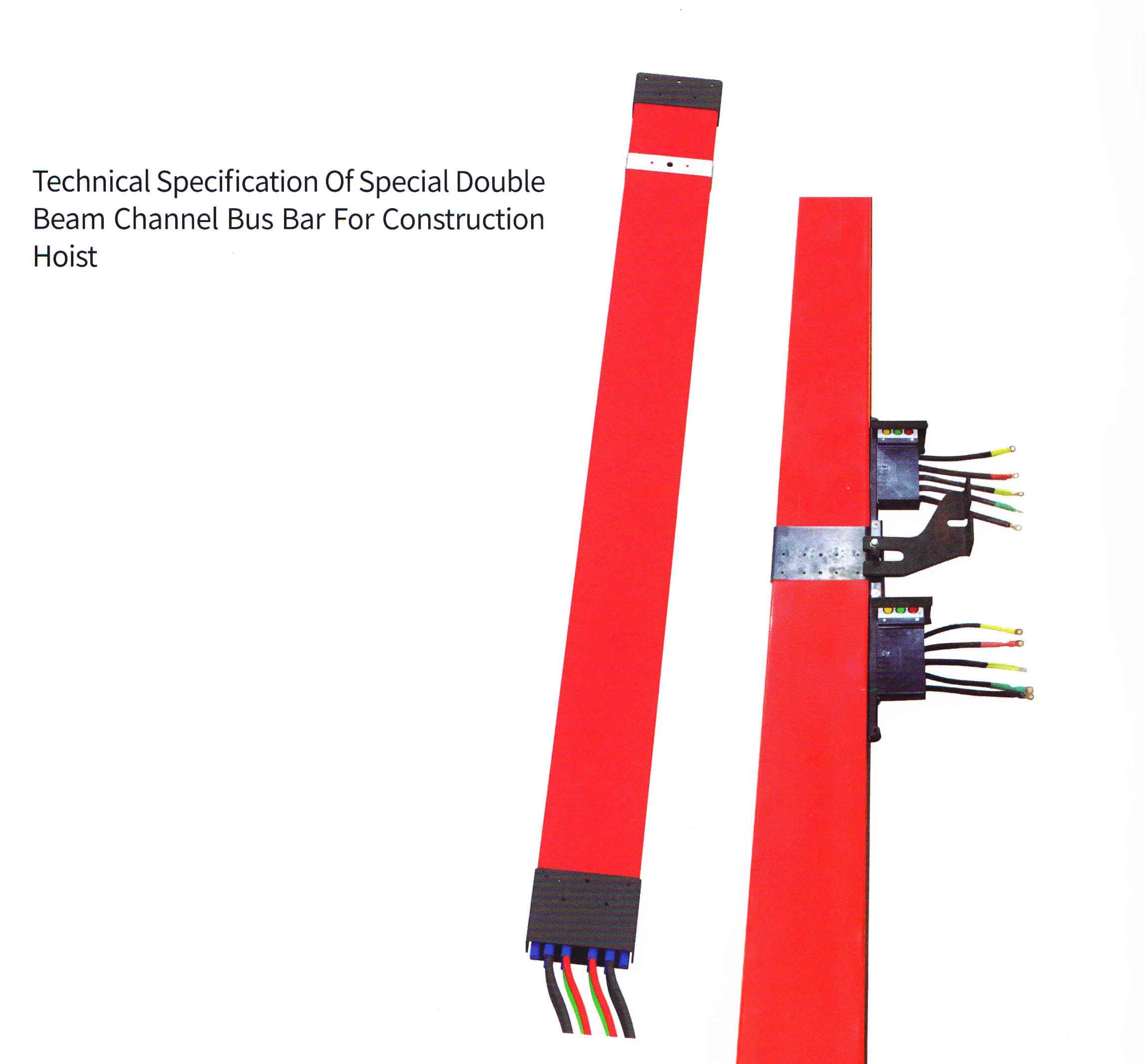
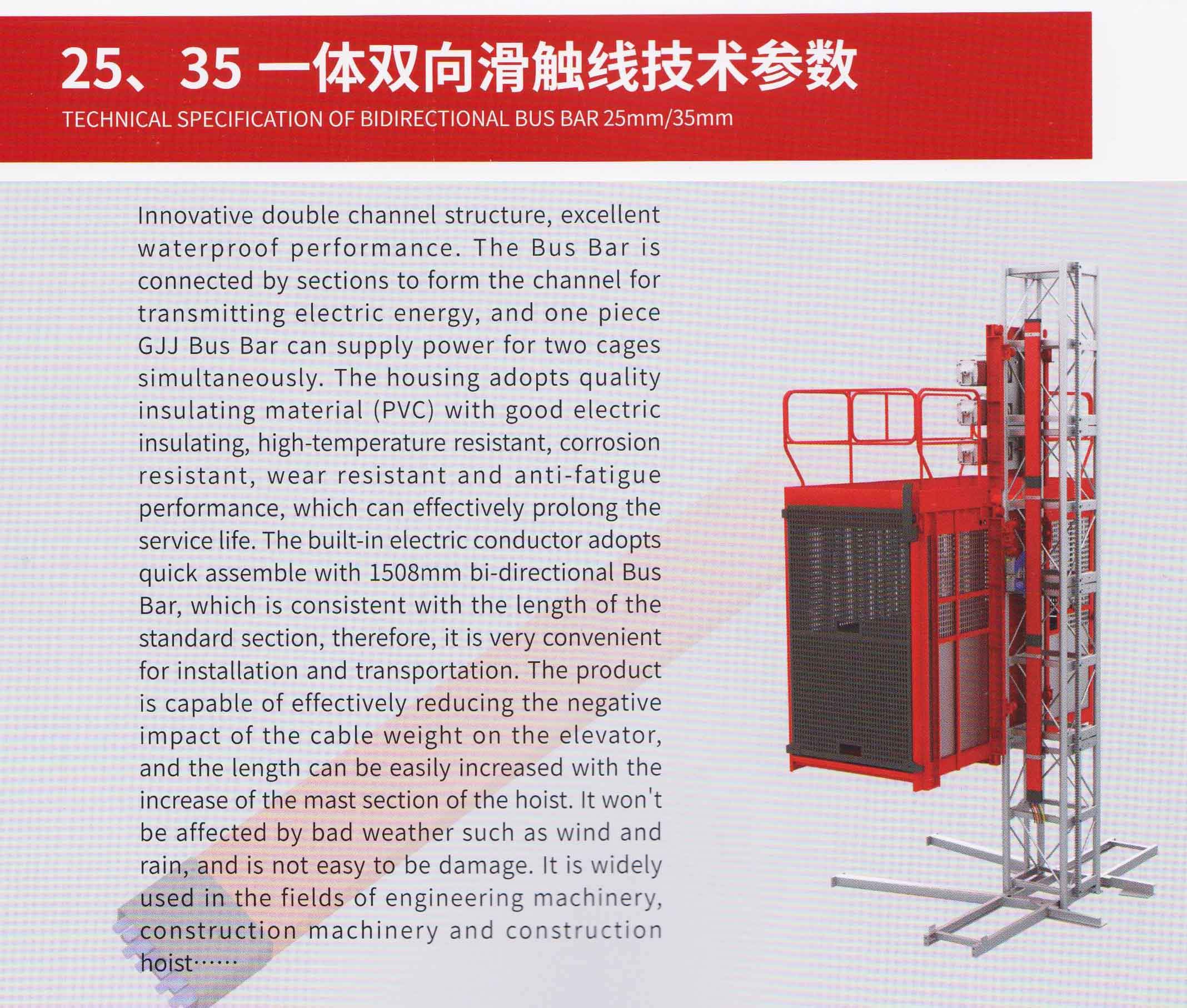
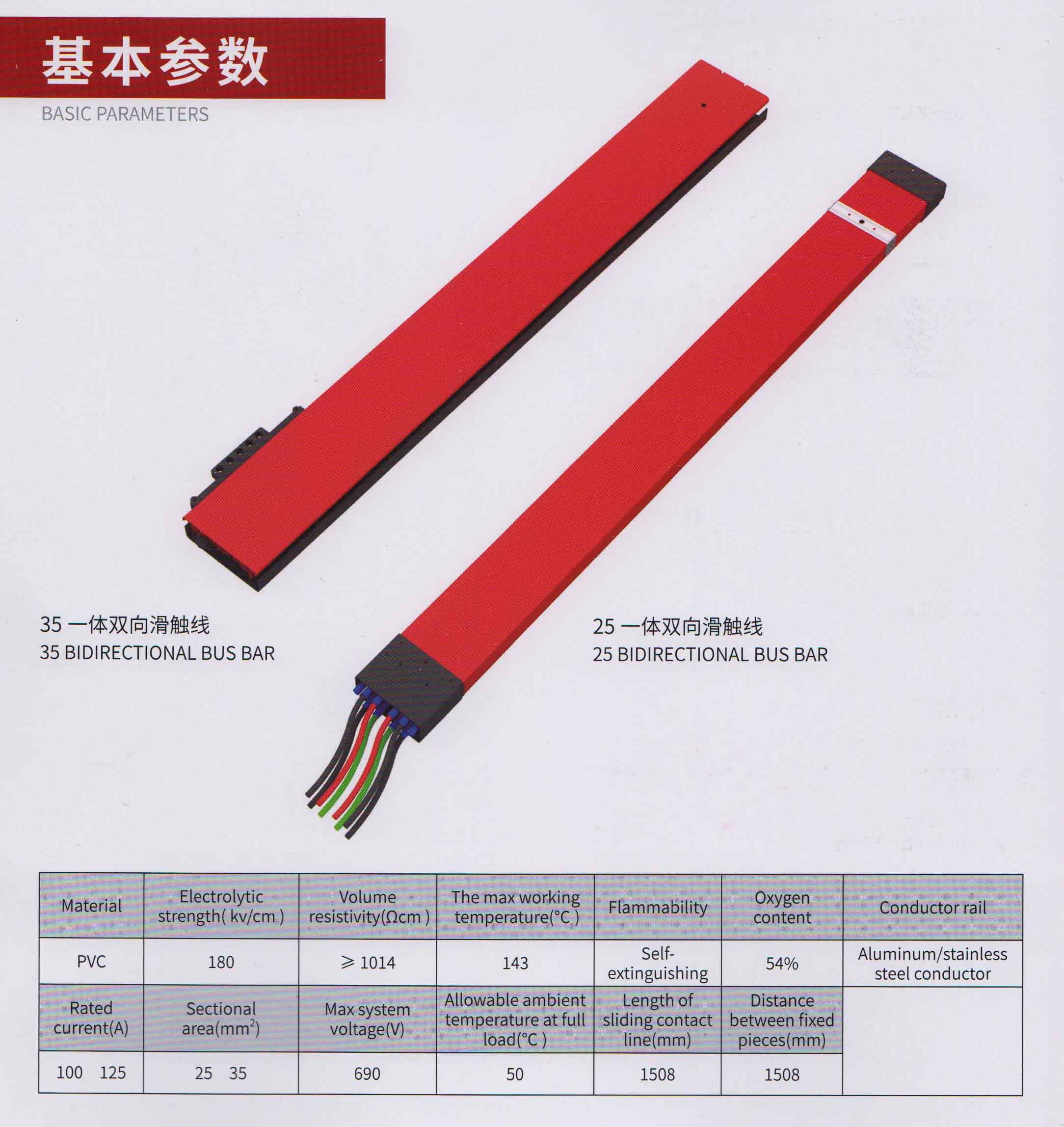
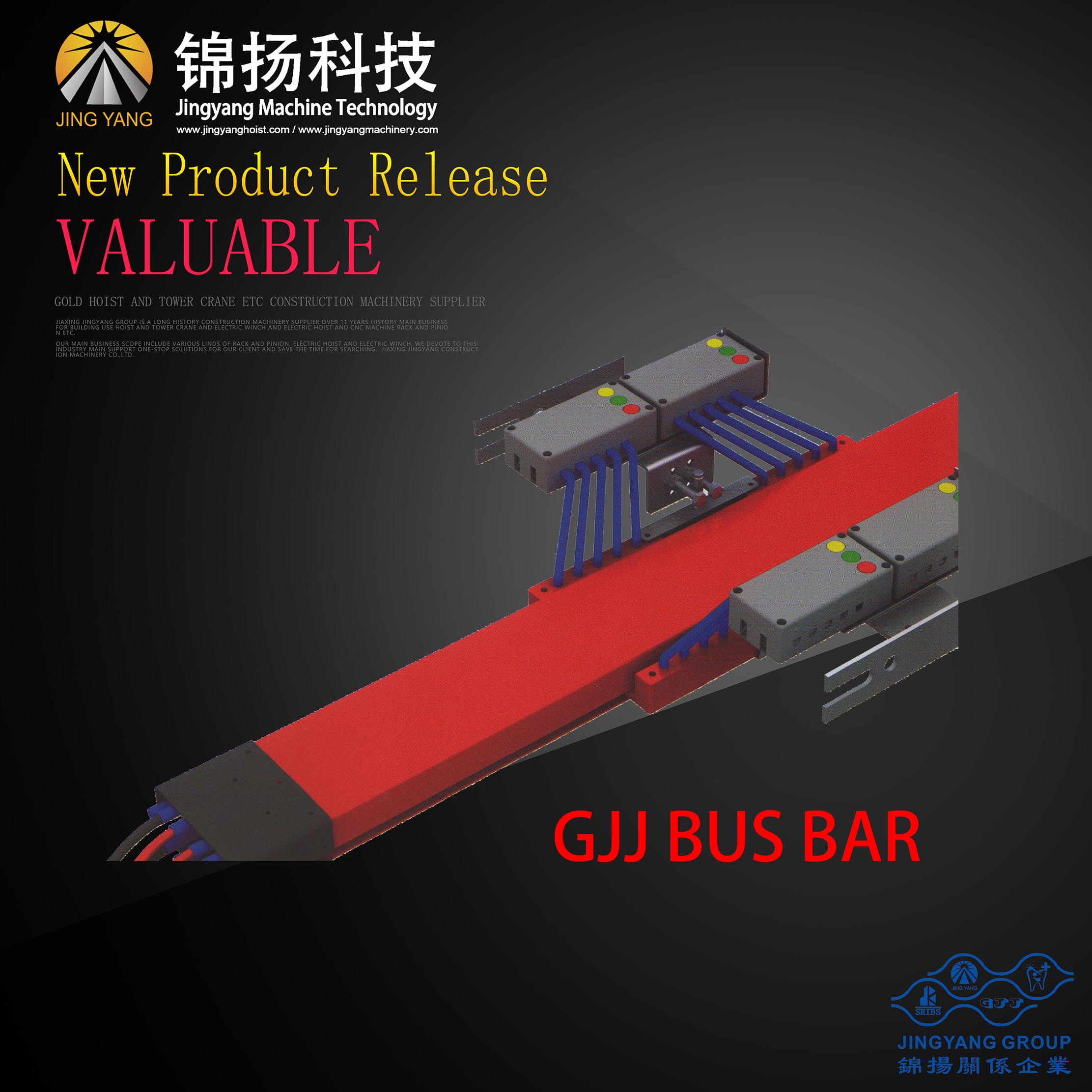
| TECHNICAL SPECIFICATION OF BIDIRECTIONAL BUS BAR 25mm/35mm Innovative double channel structure, excellent waterproof performance. The Bus Bar is connected by sections to form the channel for transmitting electric energy, and one piece GJJ Bus Bar can supply power for two cages simultaneously. The housing adopts quality insulating material (PVC) with good electric insulating, high-temperature resistant, corrosion resistant, wear resistant and anti-fatigue performance, which can effectively prolong the service life. The built-in electric conductor adopts quick assemble with 1508mm bi-directional Bus Bar, which is consistent with the length of the standard section, therefore, it is very convenient for installation and transportation. The product is capable of effectively reducing the negative impact of the cable weight on the elevator, and the length can be easily increased with the increase of the mast section of the hoist. It won’t be affected by bad weather such as wind and rain, and is not easy to be damage. It is widely used in the fields of engineering machinery, construction machinery and construction hoist |
||||||||||||||
|
||||||||||||||
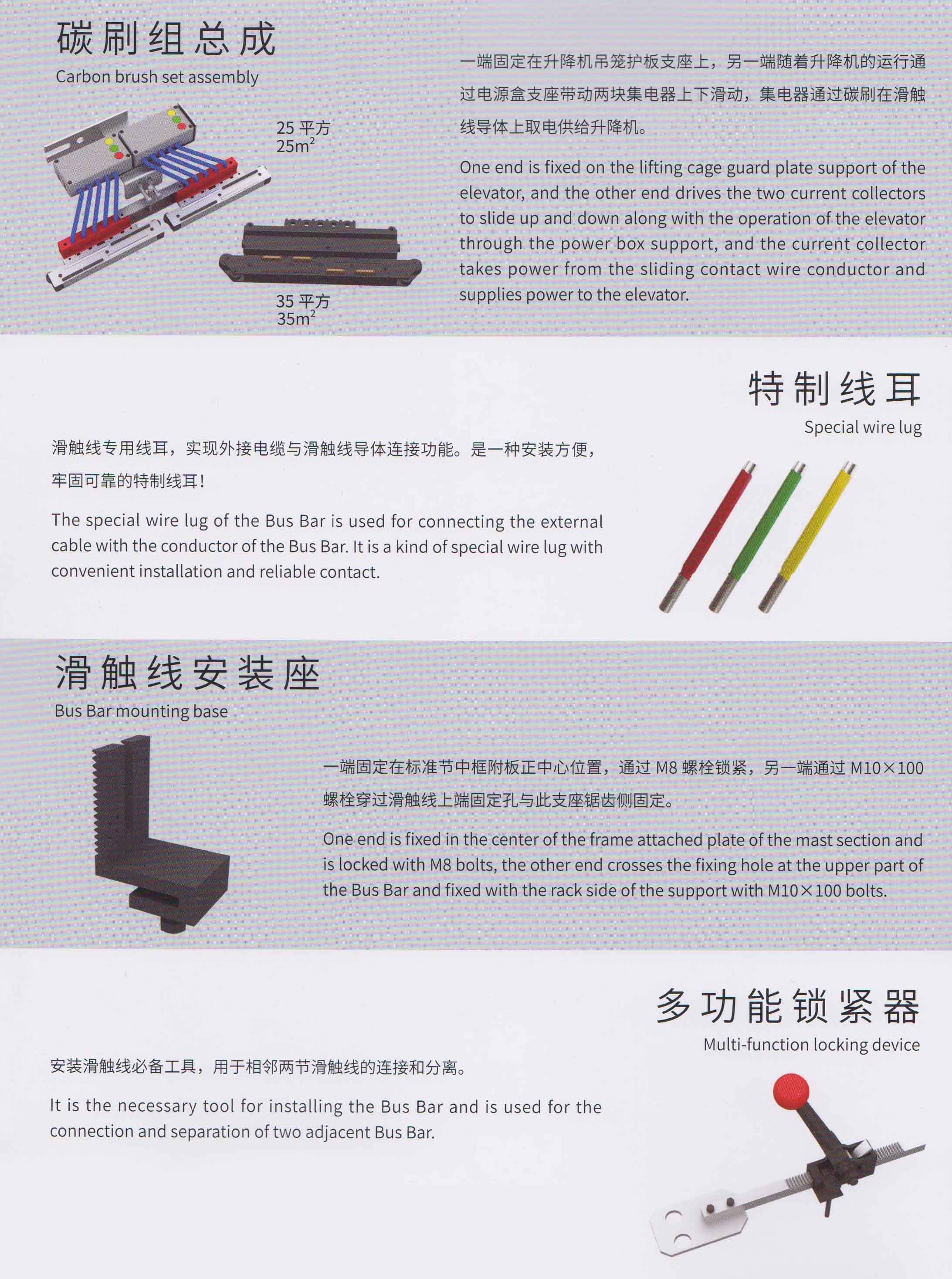
| One end is fixed on the lifting cage guard plate support of the elevator, and the other end drives the two current collectors to slide up and down along with the operation of the elevator through the power box support, and the current collector takes power from the sliding contact wire conductor and supplies power to the elevator.The special wire lug of the Bus Bar is used for connecting the external cable with the conductor of the Bus Bar. It is a kind of special wire lug with convenient installation and reliable contact. | ||||||||||||||
| One end is fixed in the center of the frame attached plate of the mast section and is locked with M8 bolts, the other end crosses the fixing hole at the upper part of the Bus Bar and fixed with the rack side of the support with M10X100 bolts.It is the necessary tool for installing the Bus Bar and is used for the connection and separation of two adjacent Bus Bar. |
| Item | Part No. | English name | Item | Part No. | English name |
| 1 | DL-0 | Cage | 31 | WG-19 | Worm gear fan |
| 2 | WG-0 | Reducing device | 32 | MAC-8 | Rubber |
| 3 | MAC-010 | Motor | 33 | WG-5 | Woem wheel |
| 4 | ZJ-0 | Mast section | 34 | WG-15 | Worm |
| 5 | XS-00 | Safety device | 35 | MAC-9 | Couping |
| 6 | HY | Hydraulic spring | 36 | MAC-020 | Pinion |
| 7 | TIE | Tie-in | 37 | ZJ100-10 | Rack |
| 8 | TL-2 | Safety device spanner | 38 | XK | Drop test operate box |
| 9 | PJ | Pipe joint | 39 | CT | Out operate box |
| 10 | BL100-G | Roller | 40 | FR | Resistance |
| 11 | BH-10 | Cable joint | 41 | PS | Waterproof plug |
| 12 | ML100-9 | Gate roller lower | 42 | SE | 3-phase swotch |
| 13 | ML100-10 | Gate roller upper | 43 | TC | Transfprmer |
| 14 | WM130-40 | Rope pulley | 44 | SDD | Annunciator |
| 15 | BS-10 | “J ” type screw | 45 | PLC | PLC Module |
| 16 | BQ-10 | Cable joint | 46 | QF | Creepage switch |
| 17 | BM-24 | Screw | 47 | SL | Limit switch |
| 18 | TL-1 | Roller spanner | 48 | FM | Belling |
| 19 | RA-9 | Adjustment unit | 49 | JS | Jacket |
| 20 | RA-12 | Brake pad | 50 | FS | Fan |
| 21 | SP | Spring | 51 | SY | EL lock |
| 22 | DL-110 | Rubber pad | 52 | F | Drop test plug |
| 23 | WG-03 | Brearing | 53 | KCE | Thermal relay |
| 24 | WG-030 | Oil seal | 54 | SQ | Braker |
| 25 | DXI-5 | Nylon wheel | 55 | KMB | Contactor |
| 26 | RA-13 | Rotary disk | 56 | BR | Brake unit |
| 27 | RA-120 | Brake piece | 57 | SPL | Speed relay |
| 28 | RA-10 | Brake disc | 58 | EL | Lamp |
| 29 | RA-7 | Electromagnet | 59 | CS | Calling system |
| 30 | CAM-3 | Counter roller | 60 | OL | Overload |
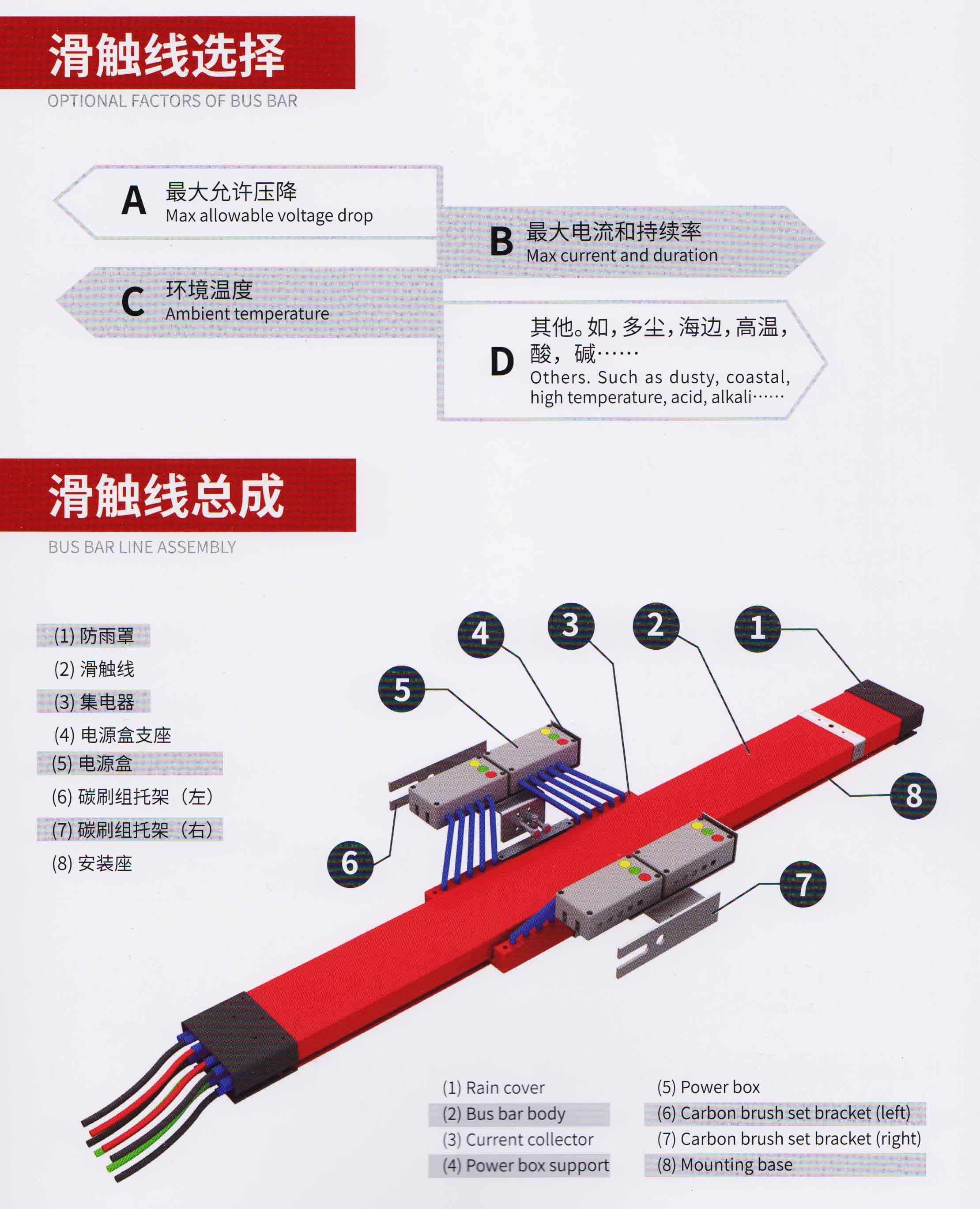
| Bus Bar assembly(1) Rain cover(2) Bus bar body(3) Current collector(4) Power box supportPower boxCarbon brush bracket set (left)Carbon brush bracket set(right)Mounting base |
| Carbon brush set assemblyOne end is fixed on the cage protection plate support of the hoist, and the other end drives the two current collectors to slide up and down along with the operation of the hoist through the power box support, and the current collector takes power from the bus bar con-ductor and supplies power to the hoist. |
| Introduction of GJJ Bus BarThe special wire lug of the Bus Bar is used for connecting the external cable with the conductor of the Bus Bar. It is a kind of special wire lug with convenient installation and reliable contact.One end is fixed in the center of the frame attached plate of the Mast and is locked with M8 bolts, the other end crosses the fixing hole at the upper part of the Bus Bar and is fixed with the serration side of the support with M10*100 bolts. |
| Multi-function locking deviceIt is the necessary tool for installing the Bus Bar and is used for the con-nection and separation of two adja-cent Bus Bars. |
| Preparation before installation:A :The installation of Bus Bar shall be completed by at least two persons.B:Necessary safety protective equipmentsC:One set of electrical tools and common wrenchesD:Considering the weather factors, avoid install in the strong windy days and rainy days |
| Installation steps of the Bus Bar:Take any one Bus Bar for the first Mast installation (power incoming wire Mast, hereinafter referred as the “incoming wire Mast”), the multi-function locking device must be used for tensioning when the Mast is connected each time. As shown in Figure 1 and Figure 2The Bus Bar mounting base is fixed at the center of the frame attached plate in the second Mast of the guide rail bracket, as shown in Figure 3, the first Mast (incoming wire Mast) fixing plate of the Bus Bar is mounted on the upper frame attached plate of the base Mast of the guide rail support (the first mast), the two waist holes of the fixed plate are aligned with two 018 circular holes at the inner side of the attached plate of the upper frame of the base mast, and fixed with M16X45 bolts (do not locking), as shown in Figure 4 |
| Upper frame attached plate of base MastFirst Mast of Bus Bar (in-coming wire Mast) fixing plateFixing plate bolt M16X45Bus Bar mounting baseMast middle frame attached plateMounting base bolt |
| The first Bus Bar Mast(wire incoming Mast) crosses the upper end fixing hole of the Bus Bar with M10X100 bolts and fixed on the Bus Bar mounting base of the frame attached plate of the second Mast of the guide rail bracket (Figure 5), and the incoming wire Mast fixing lock plate is installed, the middle and lower part of the first Mast Bus Bar (incoming wire Mast) is fixed on the fixed plate of the first Mast Bus Bar of the upper frame attached plate of the base Mast of the guide rail frame with M8X35 bolt (Figure 6), the longitudinal axis of the Bus Bar is adjusted in parallel to the guide rail frame, after all the bolts are locked, the installation of the first Mast Bus Bar is completed;First Mast of Bus Bar (incoming wire Mast)Bus Bar mounting baseM10X100 boltFirst Mast of Bus Bar (incoming wire Mast)The first Mast of the Bus Bar (incoming wire Mast) fixed locking plateM8X35bolt |
| Prepare One Bus Bar and the Bus Bar mounting seat, the Bus Bar mounting base is fixed in the center of the middle frame attached plate of the third Mast of the guide rail bracket, then the newly added Bus Bar con-ductive plate is connected with the first Bus Bar conductive aluminum strip in one-to-one correspondence, the upper end is fixed manually, the new Bus Bar is pulled in place with special tensioner, the longitudinal axis of the Bus Bar is adjusted in parallel to the longitudinal axis of the guide rail bracket, and then all the bolts and the nuts are fastened. Repeat the above installation procedure to increase Bus Bar. After the spec-ified installation height is completed, the rain cover must be installed at the top of the end Mast (Figure 7) |
| After the first Mast and the second Mast of the Bus Bar (incoming wire Mast) are fixed on the guide rail bracket, the carbon brush set plug into the top end of the second Mast (Figure 8);Manually push the carbon brush set in the Bus Bar slot, and the sliding process must be smooth and unimpeded without abnor-mal friction or abnormal noise;Disassemble the protective hook at the top of the cage, and align the mounting hole of the carbon brush bracket set with the protective hook installation holes at the top of the cage vertical beam, and then fit them, install and tighten the protective hook bolts and complete the instal-lation process (Figure 9).Cage vertical beamCarbon brush bracket setProtective hook Refer to Figure 10 and Figure 11 for the connected cable, and connect the cable to the incoming Mast of the first Mast, ensure that the phase sequence is correct, and then push it upwards till the special wire lug and the Bus Bar are connected properly. |
| Check that there is no short circuit between the phase wires, the phase wire and the zero wire and the ground wire with multimeter or magneto ohmmeter, and test the insulation resistance between each wire and the guide rail bracket which shall be more than lOOmegohm, and then connect the incoming cable with the external cage power box of the hoist.After completing the installation of the Bus Bar, connect the power wire of the hoist to the terminal box of any Bus Bar, the hoist transfers to the cage top operation, start the hoist to ascend, observe if there’s inter-ference between the carbon brush set and the guide rail bracket, the hoist is ready for operation. |
Product detail pictures:
Related Product Guide:
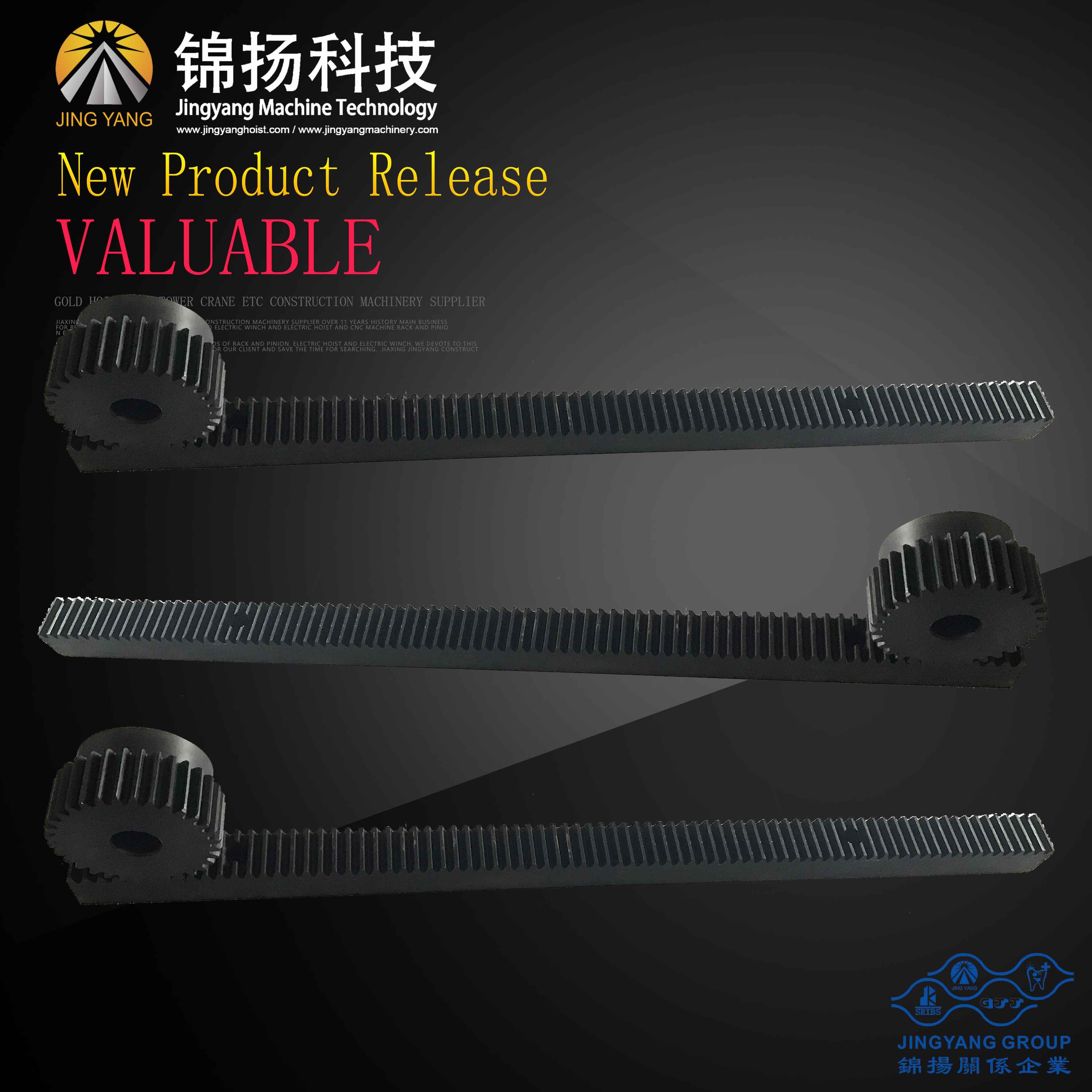
Industrial Gear Motors and Drives Market SWOT Analysis of Top Key Player & Forecasts To 2023 | Gear Rack And Pinion
Liftra blade handling device tilts big blades for easier turbine assembly | Saj30 For Construction Lifter
Our purpose would be to offer good quality products at competitive price ranges, and top-notch support to clients around the whole world. We're ISO9001, CE, and GS certified and strictly adhere to their good quality specifications for Chinese wholesale Iso Bearings To Cranes Bridge - GJJ passenger hoist slider bus bar – Jinyang, The product will supply to all over the world, such as: Juventus , Tunisia , Riyadh , Our products are mainly exported to Southeast Asia, the Middle East, North America and Europe. Our quality is surely guaranteed. If you are interested in any of our products or would like to discuss a custom order, please feel free to contact us. We are looking forward to forming successful business relationships with new clients around the world in the near future.
We guaranee our product all origional GJJ high quality item, no fake item supply.
The company leader recept us warmly, through a meticulous and thorough discussion, we signed a purchase order. Hope to cooperate smoothly
-
Original Factory Exercise Ab Wheel Roller - GJ...
-
High Quality for 12v/24v Electric Winch - GJJ ...
-
OEM Supply Electric Hoist Accessories - Constr...
-
Low MOQ for Barn Door Tracks And Rollers - GJJ...
-
Reasonable price for Plc Controller Automation ...
-
OEM Manufacturer Rack Gears Cnc Machining - CN...

